Note:
working with high voltage and batteries is dangerous and can be
lethal. Those involved with this project are trained in high
voltage safety and battery safety, and the depth of their
involvement depends on their level of engineering expertise. Do
not involve yourself in a similar project unless you are qualified and
are aware of the safety precautions that must be taken. Always
take appropriate precautions: even training and expertise does
not eliminate the possibility of injury or death.
Here we go!
The chassis comes from a Birkin S-3 car kit.
<>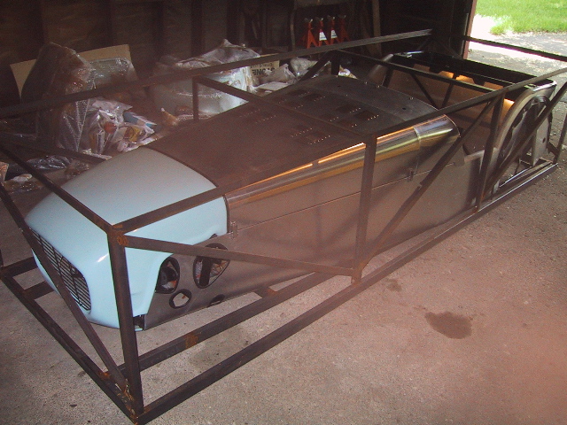
Crated Chassis
The kit comes with most of the parts needed to
assemble the car.
It is designed to be powered by a four cylinder gasoline engine, one of
the main items not included with the kit.
Kit Parts
The car will instead be propelled by an electric
Motor powered by rechargeable Batteries.
The motor is a 3-phase AC induction Motor, which can
convert over 100 horsepower of electrical power into wheel turning
mechanical power.
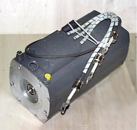
Motor
The torque and speed of the Motor is controlled by
the Motor Controller, which converts DC Battery electricity into
3-phase AC electricity to power the Motor.
The Motor Controller constantly adjusts the way this
electrical power is delivered
to the Motor,
based on the position of the Accelerator Pedal.
Additionally, the Motor Controller has a built-in
DC-to-DC Converter for charging the car's
on-board 12 Volt car battery. This 12 Volt car
battery powers the lights,
windshield wipers, and other traditional automotive
electrical accessories.
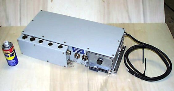
Motor Controller
152 NiMH battery modules provide power to the Motor
Controller. These battery modules were removed from
hybrid-electric cars found in salvage yards.
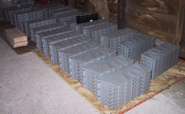
NiMH Battery Modules
The hybrid-electric car battery packs were combined
and re-engineered to provide four times the original capacity and
power.
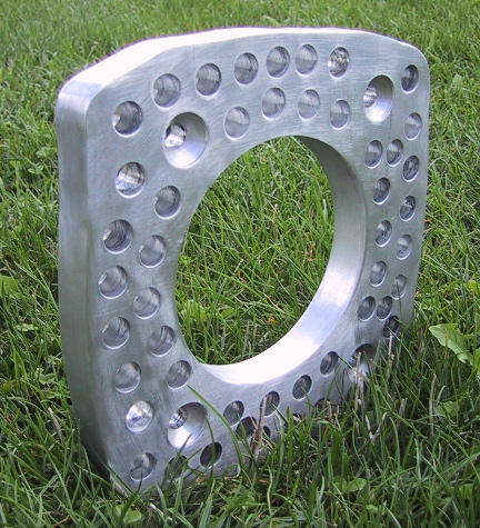
The original battery module enclosures were modified and re-used in the
creation of the Battery Assemblies.
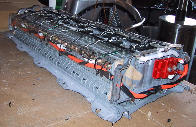
Battery Assembly
A total of five custom Battery Assemblies will power
the vehicle.
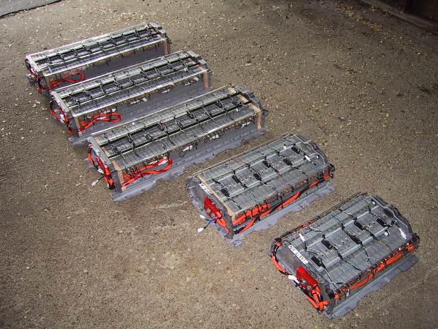
The five Battery Assemblies.
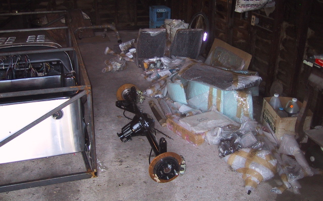
The original Birkin S-3 kit requires assembly and modification to make
the electric7 a reality.
The Chassis is seen here with Suspension and
Wheels installed.
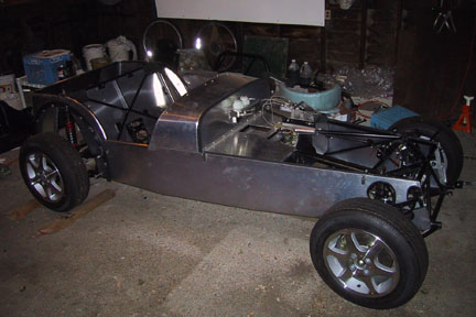
Chassis with Suspension, Steering, Wheels, and Tires.
Special low rolling resistance Tires have been selected, a type
designed for GM's EV1 electric car.
Their design extends driving range, and their
self-sealing capability
allows the spare tire to be left behind, saving weight.
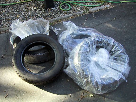
Low rolling resistance, self-sealing Tires.
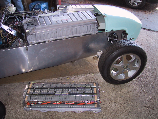
Light-weight aluminum Wheels were chosen to complement the Tires.
Is the "E" for Electric?
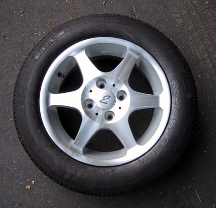
Aluminum wheel with tire mounted.
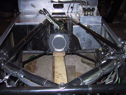
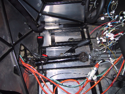
The Motor fits into the Chassis's transmission tunnel.
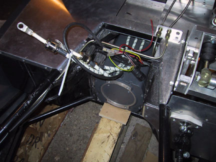
Motor in transmission tunnel.
This leaves engine compartment space available to
mount Battery Assemblies and the Motor Controller.
Engine compartment space with Motor in transmission tunnel.
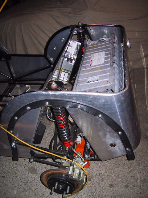
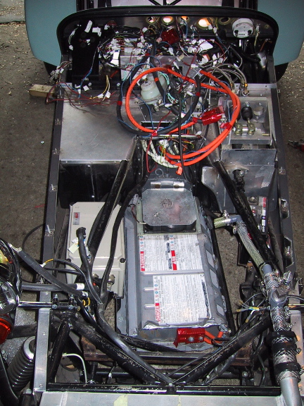
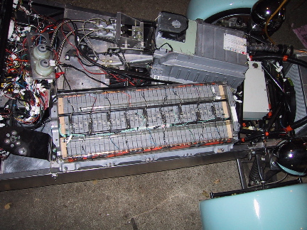
In the engine compartment area, three Battery
Assemblies are installed, along with the Motor Controller. The
top two Battery Assemblies (shown incomplete) are in their design
intent locations. The Motor Controller is visible beneath these
Battery Assemblies, and a third Battery Assembly is located below the
Motor Controller.
Front Battery Assemblies and Motor Controller.
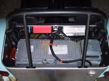
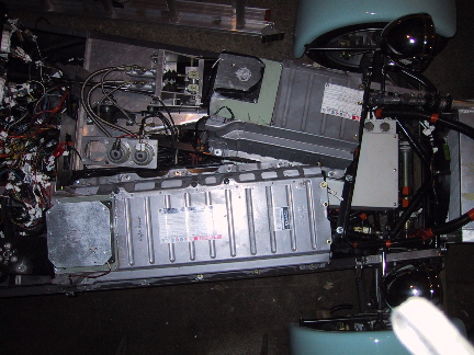
The other two Battery Assemblies are located in the rear of the car,
along with the Battery Charger.
Rear Battery Assemblies and Battery Charger.
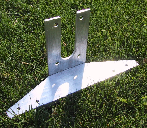
The mounting of the Battery Assemblies and Motor
Controller require a number of custom-made Mounting Brackets.
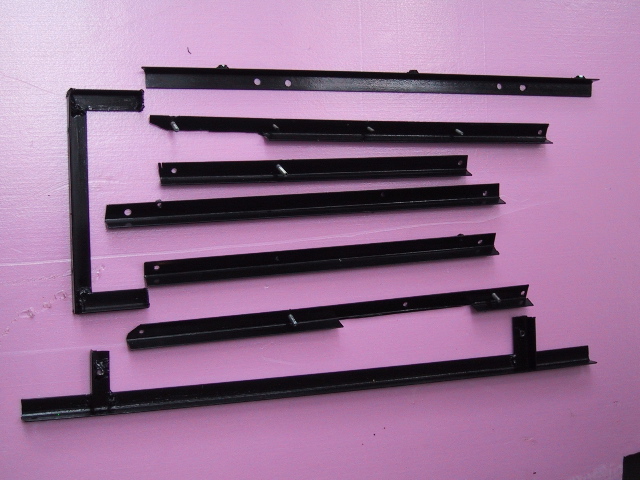
Custom-made Mounting Brackets.
The Motor requires a custom Adapter Plate and Motor-to-Chassis Mount.
Motor Adapter Plate and Motor-to-Chassis Mount.
A custom-splined Intermediate Shaft bridges the gap
between the Motor and the Drive Shaft.

Intermediate Shaft with Bearing
The Adapter Plate and Motor-to-Chassis Mount attach
directly to the Motor, and allow the Motor to be connected to the Drive
Shaft Carrier. The Drive Shaft Carrier also attaches to the
vehicle Chassis, but its main purpose is to couple to Motor to the
Drive Shaft, which turns the wheels through the rear Live Axle.
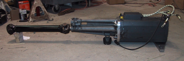
Powertrain assembly.
It is congested, but the Motor is shown installed with
the Motor-to-Chassis Mount.
Mounted Motor.
With the Powertrain fully installed, the Driveshaft
can be seen connecting the Live Axle to the Intermediate Shaft, which
gets turned by the Motor.
Assembled Drivetrain.
With the the Motor installed, the front lower
Battery Assembly gets bolted into position. The 12V Lead Acid
Battery and the Contactor Box are also attached on their welded-in
Bracketry.
Lower Battery Assembly with Contactor Box and 12V Lead Acid Battery.
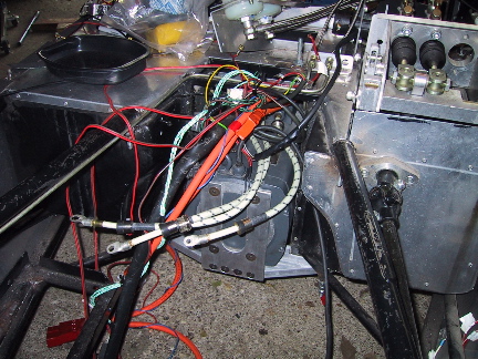
A custom-made cooling manifold connects the radiator to the Motor
Controller. Both the Motor Controller and the Motor are cooled by
regular antifreeze.
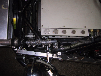
Cooling manifold connects radiator to Motor Controller.
The other end of the cooling manifold connects to the Motor.
Antifreeze gets circulated through the Motor and the Motor Controller
by an electric pump.
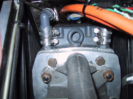
Two cooling hoses connect to the top of the Motor.
With some modifications made to the instrument panel
to accommodate their size, a Speedometer and a 10,000 RPM Tachometer
are
installed. Also shown is the headlight switch, hazard switch, and
heated windshield switch. The windshield wiper switch is ready to
be installed.
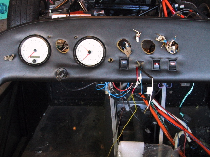
Instrument panel coming together.
All of the Instruments are now installed into the
Dashboard!
From left to right: Speedometer, State of Charge Gage,
Tachometer, 12V Battery Voltmeter, Propulsion Battery Ammeter (-100 to
+300 amps), Propulsion Battery Voltmeter (200 to 400 Volts).
Also, from left to right, Horn Button, Turning
Signal Switch, Low Brake Fluid Light (red), Turning Signal Indicator
Light (green), High Beam Switch Button, TBD Light (orange), and High
Beam Indicator Light (blue).
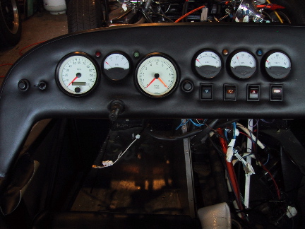
Dashboard complete with Instruments.
The next goal is to get the car ready for an
initial test drive. The center console, seats, and seatbelts are
bolted in and are ready for the drive. Carpeting and other
upholstery can be installed later. The steering wheel will be
installed once the tachometer tests out OK.
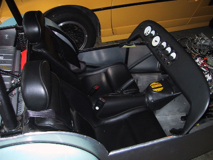
Cockpit with seats, shoulder belts, and center console bolted in.
Here is another view of the cockpit seating.
Note that the rollbar is installed behind the headrests.
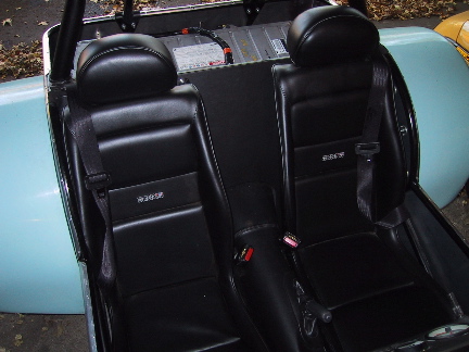
Seating area.
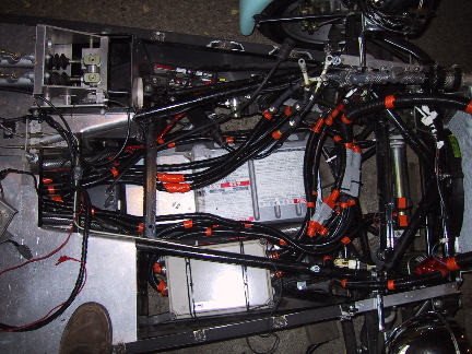
The rear compartment is ready for the first test
drive. Wiring is protected by convoluted tubing and is
restrained. Screens have been installed on battery pack air
inlets to limit debris entry. The 12V fan power supply has been
tested to power the battery fans when the 220V AC plug is connected.
Rear compartment, viewed from the top rear.
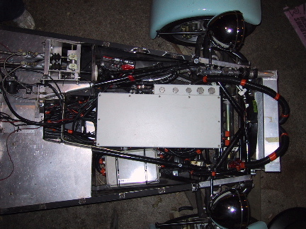
Most of the pre-test drive work remaining is in the
front section. Wiring has been put in convoluted tubing for
protection and is being routed. Above the front lower battery
pack, the
inverter can be installed.
Front compartment, viewed from the top right.
With wires routed, the inverter is bolted in place
to brackets above the front lower battery pack. Coolant fittings
are mated. Both power and signal electrical connections have been
made.
Inverter installed above front lower battery pack.
With specific modifications to allow its battery cooling fan to fit
under the hood of the car, the front left battery pack is installed on
its bracketry. It sits above the inverter, which sits above the
front lower battery pack, resulting in three layers of hardware in the
front section.
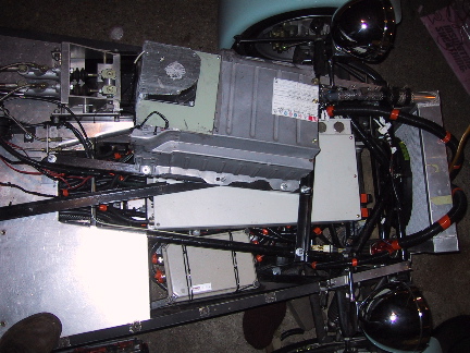
Left front battery pack installed above inverter.
The front right battery
pack sits on its mounting points, awaiting installation of its
cover. Once its cover is installed, the fan control and
temperature sensor wiring will be connected and the battery system
installation will be tested.
Right front pack partially installed without its cover.
The front right battery
pack's cover is now installed with its fan and temperature sensor
wiring hooked up. The next step will be to retest the battery
system by powering the inverter and performing a wheel spin test.
Both front top battery packs installed.
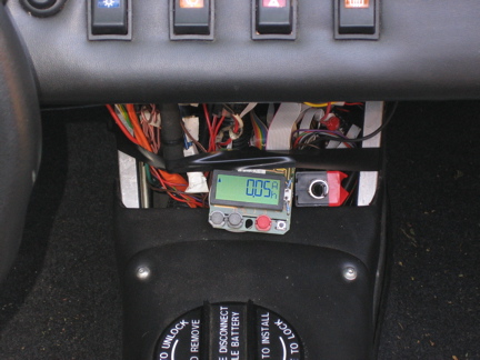
Charging!
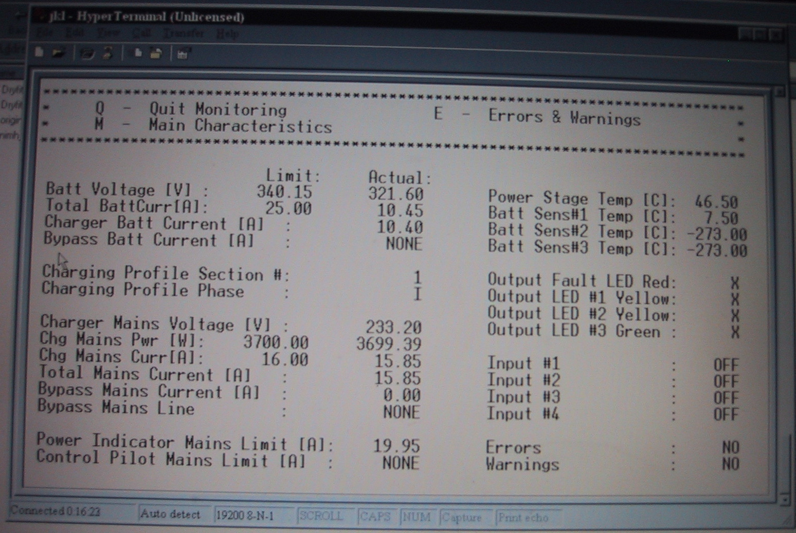
First charge monitor data.
With the help of an old laptop computer, the
charger was programmed and has now charged the batteries with 3.3 kW of
electrical power! Check out the photograph of the charger monitor
screen.
First Driving Test
On January 8, 2005, we drove the car down and back up the driveway on
its own power six times! Click on the image below to download and
watch the video of Steve driving the car! The
hood, windshield, and nosecone were not installed for this test.
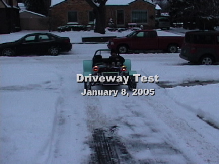
Steve drives the car up the driveway! (Click on image to watch
the Quicktime movie.)